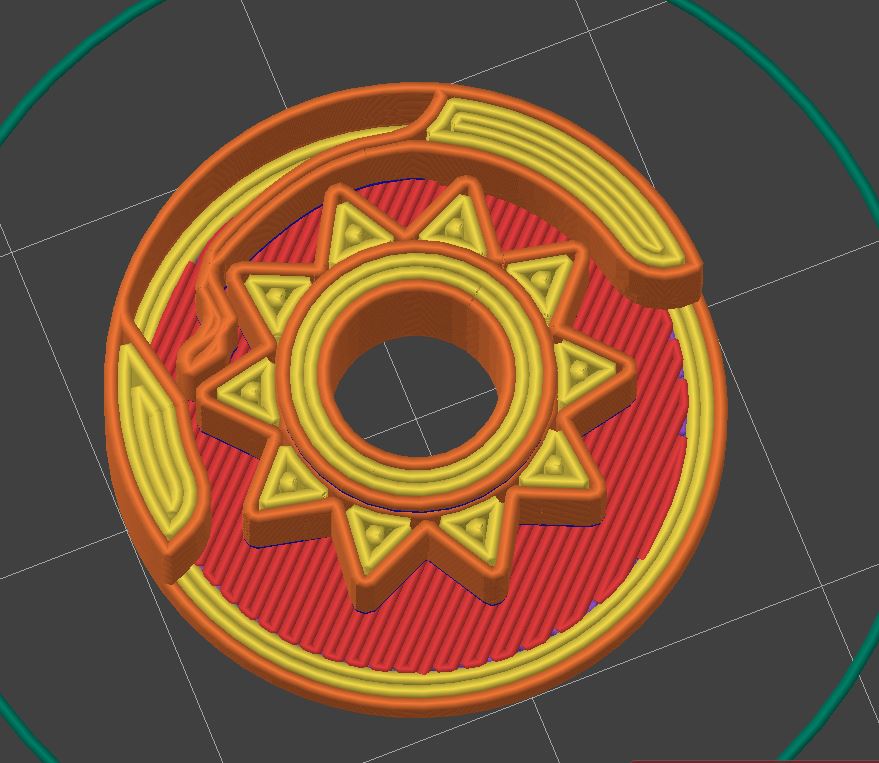
After half a dozen iterations, this was the first reasonably working, acceptable feeling, and good-sounding ratchet mechanism.
allows clockwise rotation blocks counterclockwise rotation
design features:
- allows for a large inner bore (e.g. rotary encoder shaft or 5.2mm screwdriver bit)
- printable with 0.4mm nozzle
- 2cm diameter
- no assembly required. Print in place.
To get a full ratchet: mirror the assembly and add a mechanism/part that pushes one of the springs out. In neutral both leavers are engaged and the ratchet is completely locked.
Btw. Good luck copying it without going through half a dozen of iterations. Going from it barely works to this isn’t easy. For my part: Version 5 was working and close to the final design. It took another 10 rounds to get it usable and from there some more to fine-tune it.
Hol up. Did you just make a post about this, not provide an Stl, and drop a threat /challenge about trying to reproduce it? Is this just a brag or are your trying to sell the design or something? Either way, this isn’t really in the spirit of this community.
If you consider sharing mechanical design concepts as not in line with the spirit it’s fine but others are likely interested in seeing how things work and takes it as inspiration for their designs.
Go and recreate it. Nobody stops you. Could provide the STL but wouldn’t be worth a lot as this is so dialed (tolerances) that it comes down to the specific printer/extrusion system. There are older revisions with huge tolerances (0.4mm) that work but wear down rapidly. To print this exact version it needs to be capable of printing with 0.23mm gap/tolerance between parts.
Btw. Good luck copying it without going through half a dozen of iterations.
Go and recreate it. Nobody stops you.
It’s your attitude. This post is better off in one of the functional print communities anyways.
Here you go: https://www.thingiverse.com/thing:6595547
v10 should still be 0.4mm tolerances (easy to print) on all sides and working. Otherwise not a great design but enough for you to understand that there are dozens of parameters to tune in such a “simple” mechanism and it is (nearly) impossible to nail it on the first try. Have we started talking about optimizing the force required to break it loose? That’s one more thing that needs to be accounted for.
Then post the parametrised step file so people can tinker themselves.
That said, if you did all this work and went through all these iterations to make a single ratchet that nobody else can copy then it sounds like you massively wasted your time. I would far prefer something with a tiny bit of assembly to a print-in-place gimmick that takes far more effort. The only way this makes any sense is if you’re making a lot of them.
I guess keep it to yourself in that case.
Watch your attitude.
I think you still somehow assume this is some kind of ad to sell this design for money or I am a jerk for not just publishing it with source files.
Also not everybody spends their time designing and publishing whatever is popular at the moment on Makerworld to collect points/store credit. There is a different world that doesn’t run on Fusion360 source file most people could edit and can design parts with a particular material & print(farm)/process in mind to get the most out of the FFF 3D-printing process.
WaTCh YoUr aTTItude
Lol, you got told your attitude was the problem and you just had to offload that onto me, didn’t you?
On the design of the teeth on the cog, would an alternatively shaped triangle be of any benefit? If the action/rotation only goes one way, then having one side sloped and the other side flat seems like it would work better for the stopping mechanism.
Hope I was able to explain that properly, please let me know if you understand what i mean.
The teeth is indeed a critical aspect. It has to be symmetrical as this assembly is mirrored to block the rotation in the other direction.
An alternative to this would be printing the spring with the contact surface separately and inserting it into this print (pause at layer height, insert part, continue print) allowing other geometries (that would overlap with the teeth if printed in place) and pretension. The downside is it’s a manual task and one more separate part to keep track of.
This is small and the tolerances of the center hub cause the teeths/“gear” to move approx. 0.3-0.5mm of centre. This means what you see in the CAD/slicer isn’t how it will look once printed. I had to narrow the gap down as much as I could to get the largest contact area. If you make it a sled on one side there is less material/surface area.
A further consequence is that the tip of it doesn’t touch anything as such you could remove the very tip to adjust the sound signature. The feeling is slightly changed but primarily this replaced the high-pitched plastic sound with a deep tone.
The nice aspect is that in the blocking position, it is a solid connection meaning it can take as much load as the teeth (tip) can support (hence the trying to maximize the contact area there). The spring element is only there to return this blocking “bolt” into position after a teeth passes through.
I wish I could see a visual of how it operates, because I’m sure it’s something simple about it that I’m not seeing right away.
The thing that I’m having trouble comprehending is how the symmetrical teeth design would be capable of engaging the spring/blocker (pawl?). I mean that the pawl doesn’t seem like it will be able to work as a stop; it seems like it would just allow the gears to bypass it regardless of rotation direction. Is this incorrect? I know you said there is a mirrored assembly to block the rotation in the other direction, but that still doesn’t help me understand the pawl/teeth engagement quandary that my mind has created.
The sound signature you mentioned is a nice detail that I’m glad you included. I definitely wouldn’t have thought of that right away if I was designing something similar.
here you go: https://www.thingiverse.com/thing:6595547 Likely a old version with 0.4mm clearance that does work. If not message me and I could send you a later revision with 0.23mm that definitly works.
How does it work?
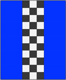
one direction: pretty obvious the spring bends out, the teeth pass through the other direction: the spring gets slightly pulled/stretched (the leading tip of the teeth pushes it) which causes the tip to be pushed against the block (left in the picture) and blocking the mechanism.
In other words, this mechanism works by having a physical path for the compression of the spring but in the opposite direction when would need to stretch to move pass the teeth it is stopped by a wall/block.
Sweet! 3d printing is a lot of trial and error, which is why I always hesitated with bigger designs.
That’s exactly why it is a partial model/design to rapidly iterate on it: 1g, 10-minute print time. The full version with all the print-in-place parts takes 16 minutes.
Another aspect is collecting designs for a library. From now on I can copy past this subassembly into bigger designs and know it will just work. If I need to modify it I know how and where to change it to get the desired outcome.
3D Printing & Using NASA Space (Ratcheting) Wrench Here on Earth - @Barnacules
Here is an alternative Piped link(s):
https://piped.video/mvr9a4aZlmU?si=wUzmfNACcnkunRBv
Piped is a privacy-respecting open-source alternative frontend to YouTube.
I’m open-source; check me out at GitHub.


