
I’ve been trying to solve an automotive electronics problem for several weeks now, but everyone I’ve spoke to can’t seem to come up with a solution.
In brief, I’m trying to add a relay in-line with the horn switch in my car, such that I can close my own circuit when the horn is pressed, without affecting the existing horn circuit in the car.
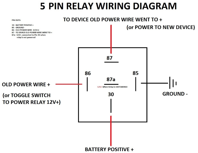
I had some JD1912 12V relays left over from a previous install, so I tried to use those. (Relevant image: Diagram)
First, I placed connected the trigger wire (pin 86) to the the wire coming into the horn switch, and the ground (pin 85). The relay triggered when the horn button was pressed as expected, but this also caused the actual car horn to sound continuously. Presumably doing this was enough to give the factory horn relay enough current to close.
Next, I tried placing the relay in series with the horn switch by splicing the wiring heading into the horn switch, and connecting the relay (pin 86 and 85) in line. Once again, the relay triggered with the horn switch as expected. However, this time, the actual car horn didn’t sound at all.
The best I can work out is that there’s a resistor in-line with the relay trigger (otherwise connecting it straight to ground would cause a short, right?) However, that resistor is just enough to allow the factory horn relay to trigger when connected to ground.
The way the car is designed, I can’t splice into the wire coming out of the switch to detect when the horn is pressed, since it’s a shared ground with other components.
My question is, is there such a thing as a relay with no resistor? Essentially all I’m looking for is a component that will “detect” current on the horn switch wire, and close a separate circuit. I’m not sure if a relay is even the correct way to go about this. Hopefully you guys can point me in the right direction.
I see. I was under the impression that there’s a seperate resistor to avoid shorts when you connect from the trigger to ground.
It’s a 2014 Nissan Altima. I’ve spent quite a bit of time trying to find wiring diagrams, but I haven’t gotten very far. I got to the point I’m at now by following some old forum posts and confirming with a multimeter. What you described sounds accurate: the horn wire under the steering column seems to always be at 12v. Pressing the horn seems to send it to ~0V, so I assume it’s just jumping to the shared ground wire. I will say that when I disconnect to horn at the front of the car (to silence it), I can hear a relay in the engine bay clicking when I press the horn. I figure that implies it’s a physical relay, rather than a computer somewhere.
This is something I’ve considered doing. The circuit I’m adding with the relay is extremely low current, so I don’t think it would be too tricky to run wires from a relay connected right next to the horn to the cabin. I can just ground the relay to the frame of the car right near the horn such that there’s minimal chance of creating a short on the high-amp horn circuit.
Here you go fam