The Wikipedia article on Steiner constructions mentions it, but doesn’t explain it, and the source linked is a book I don’t have. This has come up in a practical project.
Here’s a solution for circles with different radius that doesn’t require right angle measurement or parallel lines:
- Draw a tangent on the larger circle
- Draw two tangents on the smaller circle that intersect where the first tangent touches the larger circle
- Draw two tangents on the larger circle where the tangents from step 2 intersect the larger circle opposite to the first tangent
- Find the intersection of the tangents from the 3rd step. A line from this to where the first tangent touches the larger circle must go through the center of the two circles.
- Repeat the above with the first tangent intersecting on a different point on the larger circle. The intersection of the lines from the 4th step is the center of the circle.
Edit: visual aid
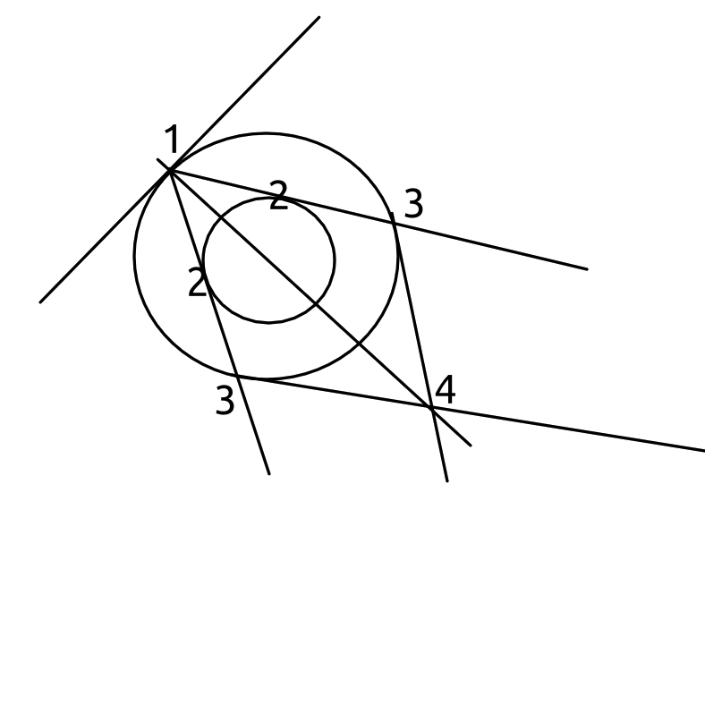
For a variation on this with fewer tangents (from A. S. Smogorzhevskii’s The Ruler In Geometrical Constructions):
- Pick point 1 on the larger circle.
- Draw two tangents (2) on the smaller circle, such that they go through point 1 and intersect the larger circle on the other end (3).
- Draw one line segment from 2 to 3’, and one from 3 to 2’. **
- Draw a line that goes through both the resulting intersection and the original point (1) you made on the larger circle. This line goes through the center of the circle.
- Repeat steps 1-4 from a different angle to get the center point.
The issue, of course, is that any tangent you draw (without other circles, lines, or tools) is going to be approximate, and so the center will also be approximate. Every solution for this that I found just assumes accurate tangents, or parallel lines, or whatever, but I don’t see a way to get those (I say, having only browsed through the topic briefly) when these two circles and a straightedge are all you have to work with. If that’s not a big deal in your practical application, cool.
–
** I’m shortcutting, here. The long version is to first draw two line segments, one that uses the smaller circle’s tangent points (2) as endpoints, and one that uses the intersections on the larger circle (3) as endpoints. Because the two circles are concentric, these segments are parallel and centered on one another, so you end up with an isosceles trapezoid. You then draw its diagonals to get its midpoint.
I’m still curious about the no-tangents solution, but for my specific application I could probably physically rest a straightedge or flat plane on the circle somehow.
Very cool, and thanks for the diagram!
That will work for me, I think, but drawing a tangent isn’t a standard straightedge operation. If Wikipedia is to be believed there’s still a “pure” solution to be found, just involving connecting intersection points.
Scribe a tangent to either circle. A line perpendicular to the tangent that passes through the intersection of the tangent must pass through the centre. Do it twice and where those two lines intersect is the centre point.
Not sure if that will work for your practical application - getting it truly perpendicular might be hard.
Exactly. I could do a straightedge construction of 90 degrees, but not until I have a center, so I’m back at square one.
Since this is a practical application (and many straightedge problems don’t allow measuring), you could do the same but with two parallel chords.
Bisect both chords and the line formed by those points must also pass through the centre.
It’s a primitive tech project, so parallel lines aren’t already available, and might be hard to construct just by neusis with twigs. Once I have a center it would be no problem, but you know, chicken and egg. Bisecting may or not be doable, depending on details - a piece of cordage could be marked with mud and doubled over on itself.
I’m pretty sure this sort of thing is why the ancients were so nuts about straightedge construction in the first place.
I mean, if you’re willing to cheat and use the length of your straightedge (assuming it’s long enough), or cordage anchored at one end, then you have a substitute compass, and the solution’s trivial.
Well, there’s a thing in the way, and I don’t have any proper rotating bearings for the straightedge. The goal is to turn a clay cone that’s as accurate as possible on a wooden stake held between awl notches in a frame. It will then be used to make future bearings. I need to ensure the edge I’m turning against intersects the axis of rotation so I don’t get a hyperbola instead. The concentric circles exist in the projection onto the plane normal to rotation.
Cordage as a compass is a possibility, but the very same flexibility that allows it to pivot will also allow it to twist and bend off the plane, so any solution based on it needs to be insensitive to that. An actual caveman, with a lifetime of doing this kind of thing, might be able to just hold a bit of the straightedge perfectly centered while it moves around the contraption, but I know I’m too clumsy.
Hmm, I wonder if there’s a 3D way to find the center of a cylinder with a spherical “compass”, which is basically what cordage is. I did look up 3D S&C constructions once before, but came up empty.
Oof, that sounds tricky, yeah. I spent some more time this morning poking around at references and testing ideas, but mostly it feels like going around in circles (no pun intended).
Do post how you end up going about it, or if you find a better solution; I’d love to know!
Alright, so I followed the same tack for a while, but the tricky thing is that a hyperboloid of one sheet is doubly ruled, which means you have to worry about secant lines corresponding in some way spuriously, just due to relation with the ruling lines. That inspired me to go in a different direction.
To make a cone, you need the wiper/striker to be coplaner with the axis or rotation; otherwise, it will become a ruling line. This is both necessary and sufficient, given that we don’t particularly care about the exact cone. Furthermore, any two non-coincident intersecting lines make a plane, and gravity offers an easy way to produce parallel lines.
You make a half-mould with a cavity that will look something like a speech bubble. The inner edge of the tail(?) will become half of the wiper, and the rest will become half of the upper beam. By reusing the mold, you can ensure the mated halves will be fairly symmetrical bilaterally, which means the center of gravity will be close to coplaner with the meeting point where the wiper forms. Some combination of filler or adhesive in between and a draw string around the outside seems like the best way to hold them together. True, that may introduce asymmetry, but with such limited tools compromises have to be made. The string or rope itself is relatively light, and with attention to detail it will still end up reasonably close to balanced.
Now you have a rigid piece with a center of gravity (roughly) coplanar to the wiper. You can use the parting line to center awl points, which will also be (roughly) coplanar. Tho only configuration of the two rotating awl points involved and the rigid body’s center of gravity which can balance is the three of them all lined up along the zenith. So, if you can balance these two components, you’ve guaranteed that the axis of rotation is the zenith, the line from center of gravity to upper awl point is the zenith. Then, the zenith is in the plane of the wiper, and so the axis or rotation is coplanar to the wiper. QED, to whatever degree that applies to caveman work.
The actual process would be very involved. The task is picky, the pieces are heavy and the top beam is probably made out of clay, which is physically delicate. The way to go is probably to sit them all in a frame with vegetation for padding, move the frame slightly away somehow, and then adjust the frame corresponding to which direction the assembly falls into the padding. It’s probably worth it to use knapped clay points for the rotating stake just to reduce sticktion. Experimentation is needed, but unfortunately I don’t really have a good place to do it.
Once you’re done, easing the beam upwards and then fixing it tightly in place will allow you so start turning. There would still be some error, of course, both from the sources I mentioned and others, but that seems unavoidable. As long as the finished product is fairly close to a cone you can rotate the resulting bearings together dry in order to lap them to a tighter fit.
In case you’re curious about the next steps, you need cones in the first place because clay shrinks when drying and firing. Two similar cones will continue to fit together after rescaling, but hyperboloids won’t. The plan then is to use the turned cone as a master for female cones, which will themselves be used to make matching male cones. The two bearings will be placed large ends together, and held on a thickened section of the wooden axle, and any stationary frame, by rope tension. The male cones will then protrude out due to being smaller, allowing clearance for the axle to continue on.
That’s really cool (and involved)! Thanks for writing that up. I hope you get a chance to actually try it.
Yes, thank you, me too, hopefully with a loose deadline. It’s an absolute ton of work just for a thing that spins, but something has to do it first if you want to bootstrap back to machines recognisably modern.
I wonder what scale would be best. Smaller is obviously easier to physically manage, but the catch is that your manufacturing error stays the same while the measurements they’re relative to decrease.
Will do!